Great article from DV Power
Introduction
DV Power TRT instruments, the true three-phase turns ratio testers, enable users to perform two types of turns ratio tests:
- simultaneous 3-phase test
- and a sequential 3-phase test.
When performing the simultaneous 3-phase test, the TRT unit supplies a true three-phase test voltage to the transformer high voltage side and measures three induced line voltages at the low voltage side. This provides the “voltage ratio” that corresponds to the nameplate ratio. When performing the sequential 3-phase test of a three-phase transformer, the TRT outputs single-phase test voltage and measures the turns ratio for each phase separately, phase by phase.
The calculated turns ratio value for certain vector groups (wye-wye, delta-delta) is the same as the nameplate ratio meaning the three-phase voltage ratio, indicated on the transformer nameplate, is equal to the ratio of a number of turns of the high voltage to the low voltage windings. For example, a 220/110 kV/kV wye-wye transformer has twice the number of turns in the high voltage winding compared to the low voltage winding.
For some other vector groups, the ratio of winding turns is not the same as the nameplate ratio. For example, for wye-delta groups turns ratio is √3 times lower than the nameplate ratio, while for delta-wye groups it is √3 times higher. When the TRT instrument calculates a deviation between the measured and nameplate turns ratio, these √3 factors are automatically taken into consideration. The user needs to input only the nameplate ratio, and it will be multiplied or divided by √3 before comparing it with the measured turns ratio.
The √3 difference is the consequence of the behavior of the three-phase voltage systems connected in delta (triangle) and wye (star). In order to make a delta-wye three-phase transformer with voltage ratio (nameplate ratio) equal to one, √3 times larger number of turns needs to be wound on delta windings compared to wye windings. For example, 173 turns on each delta winding and 100 turns on each wye winding will be necessary. In that case, the turns ratio is equal to 1.73 (approximately √3), while the voltage ratio (nameplate ratio) is equal to 1. This is because the windings in delta connection are sized to supply a line voltage (phase to phase), while the windings in wye are determined to supply a phase voltage (phase to ground). From the theory of the three-phase systems, it is known the line voltages are √3 higher than phase voltages, and they are placed by 30˚ apart. That’s where the phase angles of 30˚ (Dyn1, YNd1), 150˚ (Dyn5, YNd5), 210˚ (Dyn7, YNd7), and 330˚ (Dyn11, YNd11) come from in delta-wye and wye-delta configurations. The three-phase voltage ratio (VR), or the transformer nameplate ratio, measured with a true three-phase test voltage, is the ratio of the line voltages on the HV and LV side.
Example
The figure below illustrates the YNd1 (wye-delta) transformer.
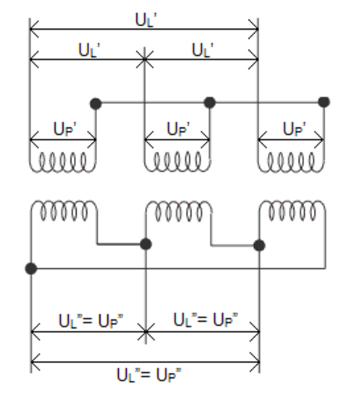
UL’ are line voltages on the primary (HV) side. UP’ are phase voltages on the primary (HV) side. Line voltages are √3 higher than phase voltages in wye-connected windings, which means UL’ = √3 * UP’.
UL” are line voltages on the secondary (LV) side. UP” are phase voltages on the secondary (LV) side. Line voltages and phase voltages are equal in delta-connected windings, meaning that UL” = UP”.
The turns ratio (TR), measured with a single-phase test voltage, is the ratio of the phase voltages on the HV and LV side.
TR = UP’ / UP”
The three-phase voltage ratio (VR), or the transformer nameplate ratio, measured with a true three-phase test voltage, is the ratio of the line voltages on the HV and LV side.
VR = UL’ / UL” = √3 * UP’ / UP”
VR = √3 * TR
Conclusions
If the ratio of winding turns (turns ratio) of a three-phase transformer is to be measured, a sequential 3-phase test should be performed. Otherwise, if the nameplate ratio (voltage ratio) of the three-phase transformer is to be measured, a simultaneous 3~ test should be performed.