Transformer Efficiency Testing
The efficiency of an ‘ideal’ transformer would be100% but in reality of course, this doesn’t exist because all transformers have losses.
Transformer losses comprise copper loss, coreloss and stray losses. As power levels of power transformers are now in the multiple MVA rating region, losses must be kept to an absolute minimum. Even 1% loss of a 10MVA transformer will result in a loss of 100kW!
Transformer Losses
CopperLoss–Copper losses would be eliminated if the windings were purely inductive,however as the windings are by nature a very long piece of wire–this will have a resistive component and as voltage dropped across this resistance it gives power lost as heat. This is often referred to as the I2R loss as Power =I2R.
Power transformers are used to transfer power from powerstation to substation;th ereason for this is that generation of power is very efficient at low voltages,while power transmission is more efficient at high voltages. This is because the ohmic losses(commonly known as‘I2R’ or ‘copper’ losses)are significant over long distances,so power is transferred at a higher voltage with corresponding lower current.
An additional benefit of reducing the I2R losses during transmission is that the conductor cross sectional area can be minimised. This does not come without the complications of handling high voltages,yet the advantages in efficiency outweigh the disadvantages of high voltage design.
Since copper loss equates to current flow raised to the power of two, this is the dominating loss with a full load test.
Core Losses (Also known as Iron loss comprising Eddy Current and Hysteresis losses.) With a fixed primary voltage, core loss can be considered to be constant and therefore this is the dominating loss with a no load test.
Stray Loss – Primarily eddy current loss in nearby conductive materials induced from Leakage inductance (also referred to as a ‘Flux leakage’) plus skin effect losses.
Measuring Losses
To measure these losses and determine a transformer’s efficiency requires a high accuracy precision power analyzer. This will illustrate the importance of certain aspects of transformer loss testing instrumentation and how the Newtons4th PPA series Precision Power Analysers have become the “Industry Standard” for transformer testing by providing an accurate solution to this field of testing.
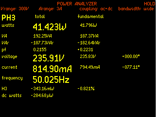
At a mains voltage of 235.83V (fundamental 50.025Hz) and 41.796 watts the transformer has a primary off load phase angle of -77.11 degrees. This is the phase angle between V1 and I0
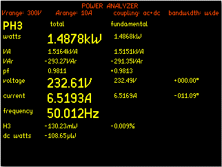
Now we have 1.4868kW, 6.5169A current and a power factor of 0.9811 (-11.09° phase angle) It must be noted that this is not quite a full load test, the transformer under test was a 1.5kVA transformer and we are testing at 1.4868kVA. In order to draw a complete vector diagram we can now test the secondary output, once the results are obtained we can now verify the theory that the impedance, the current and its respective phase angle in relation to the secondary voltage is reflected back onto the primary 180 degrees out of phase. We will also see the effect of the secondary current and its effect on the primary winding phase angle and power factor.
SecondaryWinding N4LPPA5530 Power Analyzer Readings

There is a notable difference in the two voltages on the primary and the secondary. We can see a voltage of 232.61V on the primary and 227.76V across the secondary; this is due to the voltage drop across the impedance of the secondary windings of which consists of the resistance of the windings and the leakage reactance of the windings.